Unable to render tweet. (Click to view on Twitter.)
- 1: Twitter returned an empty response.
In which I build WindEmu, an emulator for the Psion Series 5mx (a PDA from 1999 running EPOC - the OS that would become Symbian), over the course of just over a week, without access to the actual hardware. Yet another cursed project.
tl;dr links:
So, back in the days before everyone carried an iOS or Android device, people sometimes used these bizarre "personal digital assistant" things... You've probably heard of Palm and of Windows CE/Windows Mobile, but there was also a small British company called Psion making PDAs. They never quite took off in the same way as their competitors did - Palm OS was used on a variety of non-Palm devices, and Windows CE ended up on a massive amount of hardware like HP iPAQs and even on some of Palm's own devices - but they did have quite a following.
They built a few clamshell PDAs like the Series 3/3a/3c/3mx and Siena that ran SIBO/EPOC16 (a bespoke operating system) on x86-compatible CPUs, but that's merely a precursor to EPOC32, the platform that this post is all about.
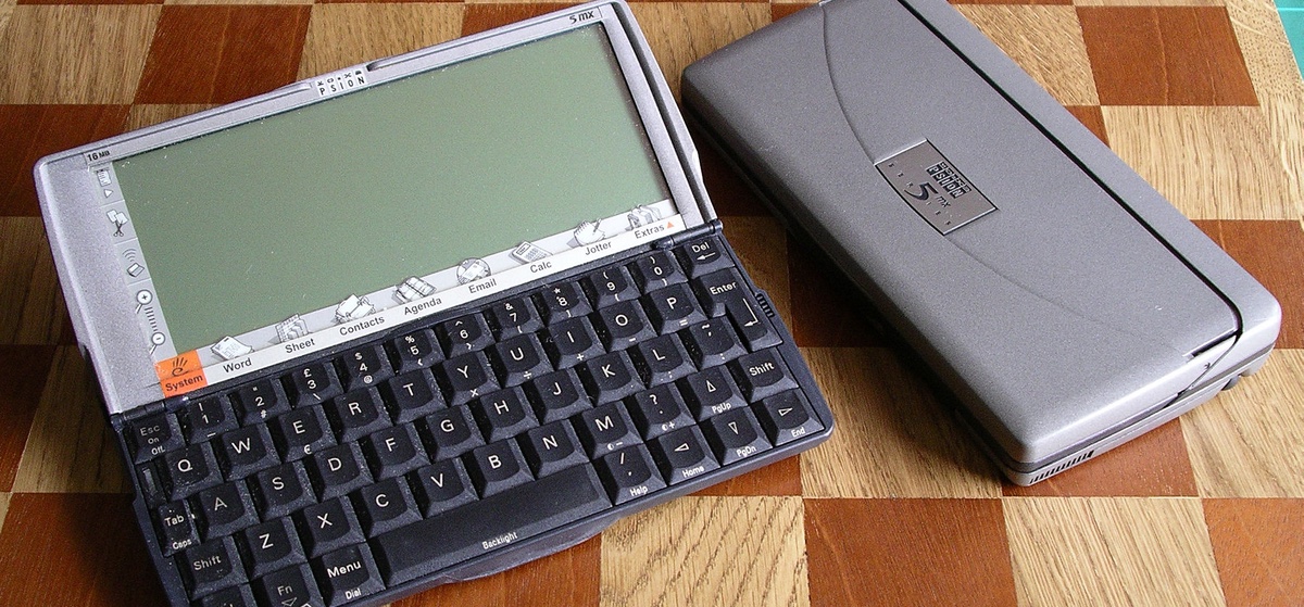
(photo by Snowmanradio [CC BY-SA 2.5], via Wikimedia Commons)
For the Series 5 (there was no 4), Psion moved to ARM chips and built a new version of EPOC - sometimes called EPOC32 - as a full rewrite using object-oriented C++. This is the OS that would end up evolving into Symbian OS, known for appearing on world-famous devices like, uh... the Nokia 9210 Communicator and the N-Gage. What a fate.
The base specs for the Series 5 - the first EPOC32 device - are as follows:
There's a few other devices, but none deviate hugely from this...
There might be more I've missed - researching obscure devices from the 90s on the internet in 2019 is surprisingly difficult!
I wanted to build something that ran EPOC as it would on an actual device. I had a few constraints... First off, I'd never written an emulator before, so this was entirely new territory for me. Also, although I own a Series 5mx, I don't have access to it right now (it's in storage in another country) so I didn't have the luxury of being able to research and test with actual hardware.
Psion, back in the day, offered an EPOC emulator as part of their SDK. I downloaded this and fired it up in a Windows XP virtual machine.
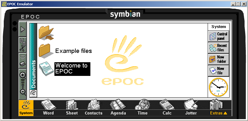
Is it cool? Yes. Is it authentic? No. This isn't actually emulating any of the real Psion hardware, an ARM CPU, or even running the EPOC kernel - it's running "WINS", which is a re-implementation of the EPOC APIs on top of Windows. Every EPOC "process" is running as a thread inside the WINS sandbox.
So, I decided I had to delve further. To have a shot at emulating anything, I first needed a ROM dump from an EPOC device. I didn't have a device on me, so I needed to find one online.
There's a piece of software called PsiROMx (archived homepage, download) which runs on an EPOC device and dumps the ROM. Useful if you have a device, but once again, I didn't!
In the end, the existence of the 5mx Pro comes to the rescue. As mentioned above, it's the 5mx variant that loads the OS from a "Sys$rom.bin" file on CompactFlash rather than having it baked onto a ROM chip. Through this, you can find a couple of different versions of it - this page links to an English version (which appears to be dumped from a regular old non-Pro), and there's also a German version which appears to have been the original shipped with the Pro.
Sys$rom.bin is a 10MB file that starts with two ARM jump instructions, followed by padding zeroes up to offset 0x80, some header data, more padding, and then code starting at 0x100. The presence of the instructions at the beginning suggests that this blob is just meant to be mapped into RAM somewhere and then executed directly. Where, though?
I found some sparse documentation pointing me to \sysdoc\cpp\e32\eumem-002.html in the EPOC C++ SDK for more guidance, which explains a bit about the virtual memory mapping exposed to EPOC processes:
Somewhat helpful, but very high-level and doesn't tell us anything specific about the 5mx hardware. Another semi-useful source of information is the 5mx code present in the OpenPsion/PsiLinux kernel, which can be checked out via CVS. Looking at include/asm-arm/hardware/psionw.h in this tells us a bit more:
The PsiLinux documentation tells us some addresses, some hardware register names and some flags, but not everything is conclusive or obvious. It appears to have been based off an official Psion document, "Windermere Software Interface Specification", which was provided to developers back in the early 00s.
"Please note that Psion gave the file to be used only for the Linux developers, and they don't want it to be publicly available. Peter Van Sebille got this deal with them, which is better than an NDA :) So please don't post it to any website or anything like that. If you don't like these terms, then just delete the .pdf file." - https://sourceforge.net/p/linux-7110/mailman/message/24934841/
Windermere is the codename for the SoC present in the 5mx. The Series 5 is based off the Cirrus Logic CL-PS7110 SoC, which has a full datasheet available (a glorious bounty of information!), but we don't have a ROM dump for it, so emulating it is futile right now.
I didn't want to poke a dead mailing list asking for a document that I might not even be allowed to have - I am not, after all, a Linux developer - so I decided to do my own research. We don't have a copy of that mysterious Boot EEPROM, and we don't know what the "Boot Flash" is, so let's just look at the Windermere/5mx ROM we do have and see what we can learn.
I threw Sys$rom.bin into IDA with the "Manual load" option and mapped it in at address 0x50000000, which immediately got me a lot of functions and valid pointers - always a good sign. The ROM is organised into a filesystem structure which is quite easy to walk; I wrote a simple IDAPython script to name every file and the different portions of the executable headers.
This got me a fair bit of insight into how the ROM is organised. There is a header at offset 0x80. System\Libs\EKern.exe file begins at offset 0x1120. Everything between those two components appears to form the 'bootstrap' code that sets up the system and eventually jumps to the EKern entry point.
I faffed about for a while trying to piece together what was going on, as if I tried to execute code from the ROM mapped at 0x50000000, it would make invalid accesses and everything would fall apart. Seemingly, I needed some kind of pre-existing setup to be in place... or did I?
It turns out I was just misunderstanding the way everything went together. It's easy to be misled because of how certain addresses mean different things depending on whether the MMU is on or off - for example, 0x80000404 can map to either the PWRCNT register, or to an address in kernel data memory.
Similarly, while most of the ROM expects to execute while mapped at 0x50000000, Windermere actually maps it at address 0x00000000, and the bootstrap code expects to execute in that context.
Here are the steps involved in booting the OS using the first function (I haven't yet investigated the second, jumped to by the vector at offset 0004), annotated with addresses from the English 5mx ROM:
Understanding this was fundamental in learning how the kernel did things, what hardware I needed to map where, and where I had issues in my emulator's implementation.
As it turns out, I didn't actually need any special setup other than the basic mapping - ROM at 0x00000000, RAM at 0xC0000000, and registers mapped as appropriate.
I don't know precisely what the second version of the boot code does - I've yet to test it! - but I suspect it may relate to the boot process used on the 5mx Pro whereby the OS is actually located in a separate region of RAM and not in a ROM chip.
I waffled a bit on where to begin with actually running the 5mx's code, as it runs a fairly old ARM variant. I originally assumed it was an ARM710a (which, notably, does not have THUMB!) but later realised I'd missed one important fact: while the Series 5 has a 710a, the Series 5mx has a 710T, which adds THUMB, some more multiplication instructions, and slightly changes the way that ARM coprocessor 15 works.
I could have built upon a base like qemu or MAME, but that would have required me to learn a bunch about how to fit things into their architecture and would have made it harder for me to build a simple proof-of-concept emulator.
For my first attempt I borrowed the ARM core from endrift's mGBA Game Boy Advance emulator, since its ARM7 is a rather close match to that present in the Psion. It didn't support the MMU or coprocessor 15, but I could hook these in.
To get the kernel to boot I needed to support a few of the interrupts and the timers - I used the datasheet for the Series 5's CL-PS7110 as a basic guide for these, hoping that Windermere's would operate in a similar fashion (which turned out to be correct). I wrote a simple loop which counted cycles, fired tick and timer interrupts as appropriate, and called into the ARM core to execute instructions.
Then I ran this, and... it did some stuff. With enough debug logging I could tell that some things were happening, and parts of the kernel were being initialised. I had to implement placeholder code for certain registers like the SPI and UART hardware where the OS was reading unimplemented registers, receiving 0xFFFFFFFF and getting stuck in a loop waiting for 'busy' flags to clear.
Unable to render tweet. (Click to view on Twitter.)
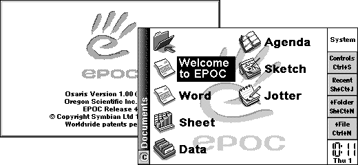
With some fixes, after 3 days I had an emulator which was successfully getting to the EPOC GUI!
To make more sense out of the hardware and how the OS interacts with it, I needed to learn more about the structure of EPOC - this is what led me to build debugging code that would hook specific parts of the OS in order to print out messages on certain events such as process creation.
Luckily, EPOC isn't entirely a black box, and there's a few things we can poke for further knowledge!
Symbian OS was open sourced in 2010. While this version of the code has evolved significantly from the late-90s variant seen in the Psion devices - the Psion kernel, EKA1, was replaced with the real-time EKA2, and support was added for many new features that weren't necessary in the Psion days - there are still a fair amount of similarities.
We also have the EPOC C++ SDK, which is much closer in age to the release present on the Psion devices. This provides a few interesting things...
strings on EPOC32/Release/MARM/Deb/EEXE.O gives you info in a somewhat human-readable 'stabs' format on structures and enumerationsHere's a pair of scripts which extract the exported names from the .LIB files and insert them into an IDA database: https://gist.github.com/Treeki/e2b5063b75c30f67b0ee9212db49d52b
None of these are a magic solution to understanding the whole OS, but information can be gleaned from each source. The names from the .LIB files annotate most of the EPOC libraries except for the kernel, as its exported ordinals are not stable across EPOC versions/devices - they work on the ER4 kernel shipped on the Osaris, but not on the ER5 kernel shipped on the Series 5mx. I expect they would work for the Series 5 if I could get a hold of that.
The stabs information takes some practice to read (in hindsight I should probably have written a tool to decode it), but explains many internal structures that are not documented in either the OSS Symbian code or the C++ SDK, such as the system calls, the kernel 'superpage', the info structures fetched through system calls and some of the device driver classes.
With my emulator booting to the EPOC GUI and being able to render the contents of the LCD buffer - the format of which was, thankfully, documented in the OpenPsion Linux kernel code - I had to then implement more hardware. It was no use without the ability to input anything!
EPOC32 will boot up successfully with surprisingly little implemented. You need a MMU, you need the Tick interrupt, you need support for the SoC's two timers (and associated interrupts), you need the RTC and you need to report some clear flags from the UART and SPI control registers. Everything else can be stubbed out and the OS will still make it to the 'desktop'.. albeit you do risk some interesting bugs if things aren't just right, as shown here:
Unable to render tweet. (Click to view on Twitter.)
The keyboard was an easy first target - and thankfully this was documented in the OpenPsion code as well. It's split into a grid of rows and columns, and the OS writes to the KSCAN register to select which column to 'scan'. Once the matrix stabilises (more of a concern on real hardware than on an emulated Psion ;p), the pins on GPIO port A represent which keys in that column are pressed. I simply store the last value written to the KSCAN register, and then compute a value for port A based off the pressed keys whenever EPOC reads it.
I ran into one small issue which required me to do some digging through EPOC's keyboard driver. According to the OpenPsion headers, specific values for KSCAN signify "all driven high" and "all driven low" - presumably this comes from the secret Windermere documentation. EPOC sets KSCAN to "all driven high" and reads the value to determine if it should do column-specific scans; presumably this is an optimisation. I returned all columns ORed together when this setting is true, and this made the keyboard work perfectly!
According to the scant docs I could find, Etna is the bespoke chip present in the Psion Series 5 and 5mx which deals with CompactFlash/PCMCIA. It appears that even the Psion Linux developers blessed with official docs from Psion themselves had no info on Etna - there are messages on the mailing list grumping about this, and the OpenPsion code is full of guesswork and random constant values from EPOC devices being written to Etna registers.
For context, EPOC abstracts most device-specific code into a "Variant" which is exposed into the system as ECust.dll.
The C++ SDK's .LIB files include some hardware-specific Variants (VARMP2, VARMPC, VARMPD) with function names referencing Etna controls like TEtna::CardReady(int) and TEtna::ModifyPc1WaitStateControl8(unsigned int, unsigned int) and TEtna::SetUartConfig(TEtna::TBaudRate, TEtna::TParity, TEtna::TStopBit, TEtna::TDataLength), but I don't have any samples matching these ordinals directly - the ECust.dll in the 5mx ROM has 86 exports, and the Osaris ROM (more on this later) has 4 exports. So, while this is somewhat interesting, I would have to do some guesswork to match up particular names to particular exports in the code I do have.
The Variant exports also mention an E2Prom class with interesting functions like DigitiserXOffset, SerialNumber and RtcCalibration - let's look at this further...
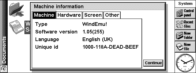
When first poking through the OS, I noticed that the EPOC Machine Info shows a 16-digit serial number - which, by default, is all zeroes. This is curious as it suggests that the Psion has auxiliary data baked in somewhere, separate from the actual ROM we're examining. It's obviously kind of important, but not so important that its absence stops EPOC from booting.
There's a serial number field in the TMachineInfoV1 structure, which can be fetched by calling the HalGet system call with the EMachineInfo parameter (conveniently, all infomation we got from the 'stabs' debug data). Following this trail leads us to the function at 0x5000DB7C in the 5mx firmware which fills up a MachineInfo structure.
Most of these bits of information are fetched through virtual methods on the Variant's main class. There's the purely-cosmetic name strings for various hardware elements that are displayed in the EPOC UI, like the screen type ("LCD"), the PSU ("APM 500") and the keyboard ("LAP 53"). There's specifications like the display size, digitiser resolution, maximum screen colours and processor speed. There's also the iMachineUniqueId, which is... simply fetched from the kernel Superpage. We must dig deeper.
I had a look through the Variant exports, theorising that even if I don't know which particular function returns the serial number, I should at least find some crumbs to send me on the right track.
There are various functions which simply read a value from the structure pointed to by iMachineData in the Superpage, and there's one which iterates through 0x80 bytes in it, XORs them together and compares the result to 0x42 - that seems suspiciously like a rudimentary checksum.
I looked at the cross-references to that checksum function, and found one which calls it, checks the result, calls a bunch of other MachineData-related functions, and even stores the Unique ID. Another puzzle piece connected!
So, this is probably our PROM. How do we give the emulated device one?
It turns out that the function call responsible for this is just above the call to the checksum function - it essentially bit-bangs various registers (some GPIO pins and some Etna registers) to read the PROM, one bit at a time. The process, from function 0x500872FC (export 44 from ECust) is as follows:
This reads 128 bytes. I implemented code to handle this reading process, and then generated a simple PROM with a valid checksum...
Etna::Etna() {
    for (int i = 0; i < 0x80; i++)
        prom[i] = 0;

    // set up the Psion's unique ID
    prom[0x1B] = 0xDE;
    prom[0x1A] = 0xAD;
    prom[0x19] = 0xBE;
    prom[0x18] = 0xEF;

    // calculate the checksum
    uint8_t chk = 0;
    for (int i = 0; i < 0x7F; i++)
        chk ^= prom[i];

    // EPOC is expecting 66
    prom[0x7F] = chk ^ 66;
}

void Etna::setPromBit0High() {
    // begin reading a word
    promReadAddress = 0;
    promReadValue = 0;
    promAddressBitsReceived = 0;
    promReadActive = true;
}

void Etna::setPromBit0Low() {
    promReadActive = false;
}

void Etna::setPromBit1High() {
    if (promAddressBitsReceived < 10) {
        // we're still receiving the address
        promReadAddress <<= 1;
        promReadAddress |= ((wake1 & 4) >> 2);
        if (++promAddressBitsReceived == 10) {
            // we can fetch the value now
            int addressInBytes = promReadAddress * 2;
            addressInBytes %= sizeof(prom);
            promReadValue = prom[addressInBytes] | (prom[addressInBytes + 1] << 8);
        }
    } else {
        wake1 &= ~8;
        if (promReadValue & 0x8000)
            wake1 |= 8;
        promReadValue <<= 1;
    }
}
And just like that, my emulated Psion now had a serial number! I also gave it a custom device name just for fun - the PROM can include one of these, which is curiously XORed with the constant key "PSIONPSIONPSION".
One of the issues I kept on grappling with was that if I tried to give the emulated device more than a certain amount of memory, I would get odd corruption where some of the sample files on the ramdisk would simply refuse to open. I had a vague suspicion that this could be caused by inaccurate emulation - the bodged-together emulation core (built upon the ARM7 code from mGBA, an emulator for a device without a MMU) didn't accurately emulate memory protection, access permissions, data aborts, or any of the caches.
In order to test out this theory, I decided to try and write my own ARM core, using the details from the ARM710a datasheet to accurately simulate all the expected behaviours of the chip from an OS kernel standpoint. Getting this to work was slightly painful - especially as it took me embarrassingly long to realise that the 5mx had a subtly different ARM710T chip - but after a couple of days of painstaking debugging I got my new core to boot into EPOC.
It was painfully slow, owing to accurate emulation of the cache and the translation lookaside buffer (TLB) - features which make the CPU faster, but ironically slow down emulation - but it was a useful proof of concept. It also did not fix the RAM disk corruption issues at all. Oops.
I'm still using my own core for the time being (with the cache and TLB disabled through preprocessor directives), but this may change later.
After seeing my progress on the 5mx emulator, on Christmas Eve, one of my friends messaged me with a picture of a dusty old Oregon Scientific Osaris they had... running none other than EPOC32 release 4 (one version behind the 5mx). I asked them to try using PsiROMx to dump the ROM, and it actually worked. I received a familiar 8MB file, which I immediately threw into IDA and ran my scripts on.
The structure was basically identical. What's more, the exported symbols from the EKern.exe file actually seem to match those present in the C++ SDK's EKERN.LIB, unlike the 5mx's kernel - a nice bonus which helped shed some more light on how the kernel does things.
Furthermore, the Osaris is not based on a custom chip, but instead uses the Cirrus Logic CL-PS7111, a variant of the CL-PS7110 present in the Series 5. Finding the datasheet for it was trivial, so I immediately had full documentation for all its registers. With kernel symbols, SoC documentation and the knowledge I'd picked up from the 5mx, porting WindEmu to run the Osaris ROM was trivial.
I did some refactoring to separate device-specific aspects into separate subclasses of the ARM710 class, and quickly built up an emulator for it.
As with the 5mx, the kernel got stuck in a loop polling unimplemented I/O-related registers. Unlike Psion's own devices, however, the Osaris eschews the custom Etna chip in favour of the standard CL-PS7600. I found a datasheet for this which explained the registers and from this I figured out how to return values that would satisfy the kernel enough to get it to keep going and boot into the OS.
Adding a second device to WindEmu actually proved to be a net win, as the extra info provided by the Osaris hardware's documentation allowed me to learn more about how the EPOC drivers are structured as a whole. I decided to try and implement the ADC (analogue-digital converter) accessed via SPI - required for the digitiser and for battery voltage monitoring.
The Osaris kernel exposes TEiger::RequestSpiSample(int, int) which writes to the SYNCIO register, and TEiger::SpiSample() which reads from it. There's a whole lot of abstraction and fluff in how these are exposed to individual device drivers, but the tl;dr is that the Variant exposes individual SPI 'channels' through string names, which are mapped to IDs internally.
The device sends a request through the SYNCIO register encoding a 'configuration byte' (the ID in question) and a couple of SoC configuration bits, some magic happens, and a while later, a 12-bit sample can be read. The SPI Controller class in the Variant takes care of all of this.
The Osaris Variant exposes five channels: DigitiserY (0x81), DigitiserX (0xC1), MainBattery (0x91), BackupBattery (0xD1) and Reference (0xA1). On the 5mx, things work a bit differently and there's four channels: DigitiserY (0x9093), DigitiserX (0xD0D3), MainBattery (0xA4A4) and BackupBattery (0xE4E4).
On the Osaris, the kernel simply waits a little bit after writing a request and then reads the expected reply back from the SYNCIO register.
On the 5mx, there are multiple responsible registers, and the request process is significantly more complex. Configuration flags are written to SSCR0. Eight bits are written to SSDR, followed by two zero writes, followed by another eight bits, followed by two more zero writes.
Following the post-write delay, the device does 4 reads from SSDR which get discarded. Two significant reads are then done. Bits 0-6 of the first read form the top 7 bits of the 12-bit result, and bits 3-7 of the second read form the bottom 5 bits of the 12-bit result. Then, the SSSR register is polled in a loop; if bit 2 is set, SSDR is read and then discarded, and if bit 2 is clear, the loop exits.
I don't understand everything about how the SPI works - presumably there are timing idiosyncrasies that would rear their head on a real device - but this info was enough to trick EPOC into reading valid values on both devices. With this implemented, EPOC no longer complains about low/missing batteries, and the basis for the touchscreen is there...
There are two missing components for touch. The OS needs to detect when the pen is down - this simply occurs through an interrupt on both devices, so that was trivial to implement. (As far as I can tell, the interrupt doesn't actually act as an interrupt - it's just used as a flag which is polled regularly. I might be wrong though, as I haven't actually tested it!)
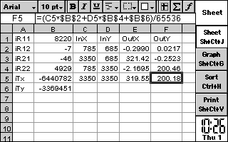
Calibration is more difficult. The Superpage stores the data as a TDigitizerCalibrateValues structure, which our stabs data reports to be the following: TDigitizerCalibrateValues:Tt(20,657)=s24iR11:(0,1),0,32;iR12:(0,1),32,32;iR21:(0,1),64,32;iR22:(0,1),96,32;iTx:(0,1),128,32;iTy:(0,1),160,32;;
This essentially decodes to: struct TDigitizerCalibrateValues { int iR11, iR12, iR21, iR22, iTx, iTy };
The OS derives screen coordinates from the ADC input using the following algorithm: x = (inputX*iR11 + inputY*iR22 + iTx) >> 16; y = (inputX*iR12 + inputY*iR21 + iTy) >> 16
The Osaris has default calibration values: { 8220, -7, -46, 4929, -6440782, -3369451 }. The 5mx has { -11515, 29, 2, -5017, 43673408, 18792120 } - but ups the ante slightly by providing factory calibration data in PROM (which I've just left blank).
I had two problems to solve here. First, I needed to generate values that the device would convert to appropriate coordinates. Second, I needed to learn what the device considered to be appropriate screen coordinates. EPOC devices have silkscreened shortcut icons - how do these factor into the coordinate calculation?
I built a simple spreadsheet to help me work out the spread of the input values and used this to derive some calculations which I plugged into the emulator. I threw in hooks to print out the post-conversion screen coordinates (as calculated by the device), and then watched what happened when I 'clicked' on specific coordinates in order to determine where EPOC was expecting certain elements such as the silkscreened shortcut icons to be.
As it turns out, (0,0) in the coordinate system represents the top left of the LCD (not the digitiser) - so for the silkscreened icons to the left of the LCD (which both the Osaris and the 5mx have, in different forms), the X coordinates are negative.
With this knowledge, I was able to implement practically perfect touchscreen support. One more beast slayed!
By this point, WindEmu could emulate the Psion Series 5mx and the Osaris to a fairly functional level - the OS works, the keyboard works, the touchscreen works. It's fairly slow, the communication mechanisms don't work (IrDA/serial/memory) and sound doesn't work, but it's a good start for a week's worth of work!
I wanted to show this off, and I figured doing it in a web browser would be a particularly cool way. I'd deliberately built the WindEmu core to run independently of Qt, so I pulled down the Emscripten SDK and tried building a web front-end...
A couple of hours and a few dozen lines of C++ later, I had the emulator running in Firefox. It's unoptimised and pretty slow, but it works!
I wanted to make it look a bit more like the real Series 5mx, so I tried to recreate the silkscreen. I was able to pull higher-resolution versions of most of the icons from a PDF of the Series 5mx manual. I gave the LCD the same greenish background that the actual device has.
You can try the result here: https://wuffs.org/WindEmu/index.html
The source code is available here (along with the core and the Qt front-end): https://github.com/Treeki/WindEmu
I'd like to take this project further, but it'll need to go on hold for a while as I need to catch up on university work. Speed is a weak point right now, especially for the browser front-end - it could undoubtedly run faster with a more optimised CPU core. Graphics are implemented in a very inefficient fashion right now, and I'd like to detect when the screen is updated so I can only refresh it when necessary, but I think I need to dig further into the LCD driver code before I can make this work.
I don't know how much of the current implementation I want to keep long-term. The CPU core is decent but others have written better and faster ARM7 cores. Now that I know more about the hardware, implementing the Psion atop a more established framework like MAME may be doable - but this will also make it harder to do silly things like throw it into Emscripten and spit out a web page.
Supporting more of the hardware, like the PCMCIA chips (and that cursed Etna) would be good. I'd also like to support some of the other EPOC32 devices if I can get hold of ROM dumps for them, like the Series 5 (CL-PS7110-based, so very similar implementation to the Osaris) and the Revo (reportedly Windermere-based).
Searching the Wayback Machine for downloads on the Psion website (filter by .zip) provides us downloads for NetBook ROM images (nb_450uk.zip, etc) and NetPad ROM images (netpad OS r166.zip, etc) which may prove to be interesting - I'd really like to try and poke at those. From a cursory look they've just got a 256 byte header plonked on the start and follow the same standard format if that is trimmed off (ARM jump instruction at 00000000 and all), and the NetPad image promises some Extra Fun as it includes a FPGA executable as well.
I said I wanted to take the project further, but that hasn't really happened. I experimented with putting support into MAME, which ended up being reimplemented and cleaned up by Ryan Holtz as the 'psion5' driver.
This is where it ends for now, unless I eventually end up getting another burst of motivation to poke at this. Perhaps someday..?
Previous Post: Pulling apart the Cosmo's SystemFOTA updater
Next Post: Researching the Digitime Tech FOTA Backdoors