Mouse Adventures #7: Writing an IDA Processor Module
Wherein I use IDAPython to put together a processor module for the Holtek HT68FB560 MCU, so I can properly disassemble my mouse's firmware.
The Series So Far
- #1: Introduction
- #2: Extracting the Firmware
- #3: Writing a Disassembler
- #4: Writing a custom tool
- #5: Dumping and Parsing the USB Descriptors
- #6: Enabling the Bootloader
Last time, I tried to figure out how to enable the bootloader through hardware means, but gave up as I was nervous about poking at the pins too much (having very little hardware experience) and didn't want to damage the mouse further. I decided to go back to reversing things on the software side, in the hopes of gaining some insight that might allow me to find out why my mouse isn't responding to commands.
Back to IDA
Trying to manipulate a disassembly in a text editor is exceedingly painful. It's fine if you're just trying to figure out a function or two, but not when you're trying to make sense of 32KB of firmware. This is where interactive tools like IDA come in. You can annotate things as you discover them, and change those annotations when you realise you made a mistake. You can easily see what references a particular register or a particular function.
The bad news: IDA doesn't support this obscure microcontroller architecture. The good news: IDA has a plugin architecture. The other bad news: the SDK is miserable to work with. It's better than nothing, though.
IDA includes Python bindings which make it a little more tolerable. There's bindings to all of the C++ APIs exposed by the SDK to regular old C++ modules/plugins, there's bindings to functions provided by IDC (IDA's built-in scripting language), and there's also some Python-specific wrappers. I generally stick with the C++ APIs because they expose all the functionality (not just a subset of it) and seem to be slightly better documented.
For this particular task, we want a processor module that tells IDA how to decode and analyse Holtek microcontroller code. We might eventually want a loader (that recognises MTP files and loads them into IDA), but we can do without it for now, as we've got a raw dump of the program code and all we need to do is map that into a fixed memory address.
Building a Processor Module with IDAPython
The IDA SDK doesn't include much in the way of documentation. You get a bunch of example modules in C++, a Python template (module/script/proctemplate.py), and a couple of Python example modules for TI MSP430 processors and for EFI bytecode.
I was a fool and tried to look for info online, which confused me further. There's a post on the IDA developers' blog called Scriptable Processor modules which purports to explain the basics and provides some simple example code. This looked very different from what I was seeing in the actual IDA SDK's examples, to the point where there was no possible way that code could work.
I found a few different examples on GitHub and tried to start drafting some code based on the common elements I saw between them. Eventually, I was able to produce something that kind of worked, and I kept on hacking on it.
You can find the resulting processor module in my GitHub repository for this mouse RE project: Treeki/TM155-tools. It's just over 500 lines of code, and a bit dirty, but it works.
Defining the Processor
The first step is to create a subclass of processor_t and define a bunch of properties inside it. These mostly map directly to fields in the C++ processor_t class, with one big exception - the assembler field is a Python dictionary with items mapping to entries in the C++ asm_t class.
class HoltekProcessor(processor_t):
    id = 0x8000 + 420

    flag = 0 # for now?

    cnbits = 16
    dnbits = 8
    segreg_size = 0
    tbyte_size = 0

    psnames = ['htkFB560']
    plnames = ['Holtek HT68FB560']

    assembler = {
        'flag': AS_COLON | AS_N2CHR,
        'uflag': 0,
        'name': 'Holtek Assembler',
        'origin': 'ORG',
        'end': 'END',
        'cmnt': '#',
        'ascsep': '"',
        'accsep': "'",
        'esccodes': '"\'',
        'a_ascii': 'DC',
        'a_byte': 'DB',
        'a_word': 'DW',
        'a_bss': 'SPACE %s',
        'a_equ': '.equ',
        'a_seg': 'seg',
        'a_curip': '$',
        'a_public': 'public',
        'a_weak': 'weak',
        'a_extrn': 'extern',
        'a_comdef': 'comm',
        'a_align': 'ALIGN',
        'lbrace': '(',
        'rbrace': ')',
        'a_mod': '%',
        'a_band': '&',
        'a_bor': '|',
        'a_xor': '^',
        'a_bnot': '~',
        'a_shl': '<<',
        'a_shr': '>>',
        'a_sizeof_fmt': 'sizeof %s',
        'low8': 'LOW %s',
        'high8': 'HIGH %s'
    }

    # we never use CS or DS but it seems like IDA expects us to
    # provide /something/ for reg_code_sreg and reg_data_sreg, so...
    # have something!
    reg_names = ['A', 'CS', 'DS']
    reg_first_sreg = 1
    reg_last_sreg = 2
    reg_code_sreg = 1
    reg_data_sreg = 2

    # the start 'itype' (arbitrary instruction type ID) we expose
    # we generate instruc (list) and instruc_end (last itype) in __init__
    instruc_start = 0

    def __init__(self):
        processor_t.__init__(self)

        self.instruc = []
        for insn in INSN_DEFS:
            self.instruc.append({'name': insn[IDEF_MNEMONIC], 'feature': insn[IDEF_IDA_FEATURE]})
        self.instruc_end = len(INSN_DEFS)
        self.icode_return = 3   # ret. We should dynamically compute this index, really
Every module must have an ID - third-party modules (like mine!) are obliged to start in the 0x8000 range. Every module has flags that control a wide range of behaviour in the IDA kernel; these include things like "supports 32-bit addressing", "stack grows up", "user can't move segments", "has delayed jumps/calls", "has conditional instructions". I read through the entire list and decided none of them seemed relevant to me.
cnbits and dnbits let you define how many bits are in a byte for code and for data segments, respectively. I picked 16 and 8 to try and match the Holtek MCU's behaviour as closely as possible: the program memory is word-addressable, so we want addresses inside IDA to represent that.
segreg_size and tbyte_size are irrelevant to our processor, as we don't have segment registers or long doubles (apparently tbyte is what IDA calls a long double, internally).
psnames and plnames allow a particular module to support multiple types of processors. We could use this to support the three different variants of this MCU, but let's keep it simple for now and just support one.
assembler contains a whole lot of properties defining what the assembly output looks like in IDA. This is why for some processors you get .word 0x1234 and for some you get DW 1234h. We're not aiming to generate something you can feed straight back into the Holtek assembler, we just want it to be understandable, so there's no need to stress too much about that bit.
The fields starting with reg_ are for configuring registers. This MCU is weird in that almost all of its registers are really just special memory locations; IDA's setup is clearly designed for more common architectures (think, for instance, of how x86 has eax, ebx, ecx, edx, ebp, and so forth). The Holtek MCU only has the accumulator A. Even the venerable 6502 has A, X and Y...!
We have to tell IDA about what instructions we support. Each instruction is assigned an arbitrary ID called the itype; we use the instruc_start and instruc_end fields to tell IDA what number range our instructions fall within, and the instruc list to give it metadata about those instructions. This just includes the instruction name and a 'feature', which is a set of flags defining how the instruction operates.
I build these up using fields located in INSN_DEFS, which is an array I've defined that contains those as well as some other useful properties used by my helper functions inside the module.
Finally, you need to tell IDA about your processor_t subclass. This is simple: define a PROCESSOR_ENTRY function that just returns a new instance of your processor class.
Notifications
There's a lot of events you can handle inside a processor module, and this happens by implementing methods in your class with specific signatures. Most have names starting with notify_, but not all. There's Python templates for these in the SDK's module/script/proctemplate.py and there's also some information in the event_t enum in include/idp.hpp. For some reason I haven't figured out, there's subtle differences between some names between C++ and Python, like ev_ana_insn becoming notify_ana. I guess you can't make it too easy.
All are optional, with the exception of four: notify_ana decodes and analyses an instruction on its own, notify_emu performs analysis tasks that may involve multiple instructions/addresses, notify_out_insn tells IDA how to display an instruction as a whole, and notify_out_operand tells IDA how to display an instruction operand.
Implementing notify_ana
This is pretty easy. You're passed an insn_t instance, containing the address of the instruction in its ea property. You ask IDA for the byte(s) at that address and set the size property to the size of the instruction. (The insn_t class provides helper methods for this, but they don't work with processors where 'byte' is over 8 bits, and that's precisely what I've done, so I couldn't use those.)
Then, you decode the instruction and put its itype into the itype property, and put details about its operands (if any) into the Op1, Op2, ... fields. Pretty straightforward. If it succeeds, you return the amount of bytes in the instruction. If it fails, you return 0, and IDA refuses to turn that particular instruction into code.
Implementing notify_out_insn and notify_out_operand
There's not much going on here. For the former, you're passed an outctx_t instance. For the latter, you're passed outctx_t and also op_t (this is the exact same object as insn_t.Op1 and company!). The outctx_t object contains methods that generate the output.
You can output arbitrary text using it, but for IDA to work best, you need to make sure you call the most appropriate methods. If you have an operand containing an immediate value (like mov A, 69), don't just spit out the number, call ctx.out_value(op), and IDA will allow you to change that number to different representations like decimal, hex or even an enum member.
Implementing notify_emu
This function receives an insn_t instance; it'll contain the info you generated inside notify_ana. Despite the names, this is really what makes all of the fancy analysis stuff possible. You can get away with leaving it empty and simply returning 1 for an initial draft, which is what I did when I was trying to get notify_ana and notify_out_* right, but you'll definitely need a proper implementation for a usable processor module.
At the very least, you'll need to make sure that you create code references (using add_cref) and data references (using add_dref) correctly. It's an easy concept but the nuances are quite hard to get right. I implemented the following rules:
- All instructions except for
halt,ret,retiandjmpcreate a flow code ref to the instruction directly afterwards as the processor executes the following instruction when the first instruction is done- (this is necessary for IDA to convert whole blocks of instructions at once, rather than doing them one-by-one)
jmpcreates a jump near code ref to its target addresscallcreates a call near code ref to its target address- All instructions that read from memory create a read data ref to that memory address
- All instructions that write to memory create a write data ref to that memory address
Memory Mapping
There's one thing I've glossed over so far. With the setup as we've described it so far, we get a single code region (0000 to 3FFF), which is what we map to the MCU's program memory. That only covers half of the story: the MCU also has data memory. Six banks worth of registers and plain old RAM, ranging from 00 to FF in each bank. How do we deal with this?
The answer is to be crafty with segments. IDA has two kinds of addresses: the linear address (this lies within 00000000 to FFFFFFFF for the non-64 variant of IDA) and the virtual address. We've got to use distinct regions of the linear address space for the Program and Data memories, but this doesn't have to be the case for the virtual address space!
Furthermore, we told IDA that bytes inside code sections are 16 bits wide, and that bytes inside data sections are 8 bits wide. We can say whether a particular segment is code or data, so this perfectly replicates the distinction in our MCU where a single address refers to one word in program memory and one byte in data memory.
We should have some code that automatically creates this segment.
    def _ensure_ram_segment_exists(self):
        segm = get_segm_by_name('HTRAM')
        if segm:
            self.ram_addr = segm.start_ea
        else:
            # alright, we want to create our RAM segment
            # find some space to do that in
            ram_size = 0x100 * BANK_COUNT
            ram_start = free_chunk(1, ram_size, -0xF)
            ram_end = ram_start + ram_size
            segm = add_segm_ex(ram_start, ram_end, ram_start >> 4, 0, saAbs, scPriv, ADDSEG_NOSREG)
            set_segm_name(ram_start, 'HTRAM')
            set_segm_type(ram_start, SEG_IMEM)
            self.ram_addr = ram_start

    def notify_newfile(self, fname):
        print('NewFile: %s' % fname)
        self._ensure_ram_segment_exists()

    def notify_oldfile(self, fname):
        print('OldFile: %s' % fname)
        self._ensure_ram_segment_exists()
This method runs every time a database is opened, thanks to the event handlers. We check to see if a segment called HTRAM exists. If it does, then we record its linear address (this is used in our notify_ana implementation when we decode operands pointing to memory). If it doesn't, then we use IDA's free_chunk function to find some free space in the linear address space, and create an appropriate segment.
This is all we need to have a region for data memory! When we load the firmware code, we end up with the default 'ROM' (program memory) segment at 0000..3FFF, and the data memory segment gets assigned linear addresses 4000..45FF. However, since we told IDA that the base was 4000 (this is what the ram_start >> 4 argument to add_segm_ex does), what we actually see are addresses starting from HTRAM:0000. Perfect.
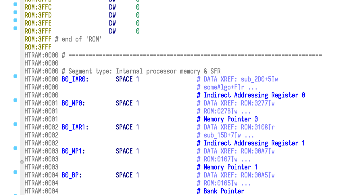
Pre-Defining Some Registers
Most of the first half of each bank is dedicated to registers with fixed locations. We know that [06h] is always going to hold PCL (Program Counter Low) and that [67h] is always USR (USB endpoint accessed detection). With notify_emu setting up our data references using add_dref, IDA automatically recognises them as memory locations, but it doesn't know what they are. Let's fix that.
I created a JSON file containing the short names, long names, bits and applicable banks for every register, based off the HT68FB560.inc file. Inserting them into the database is simple: after we create the HTRAM segment, we can just go and put that stuff in. For good measure, let's name the interrupt vectors too.
# in the global namespace
with open(get_user_idadir() + '/procs/ht68fb560.json', 'r') as f:
    REG_DEFS = json.load(f)

# ... further down ...
class HoltekProcessor(processor_t):
    def _prepare_db(self):
        # fill all the register info in
        for bank in range(6):
            prefix = 'B%d:' % bank
            for offset, reg in enumerate(regs):
                if reg and ('banks' not in reg or bank in reg['banks']):
                    ea = self.ram_addr + (bank * 0x100) + offset
                    MakeByte(ea)
                    MakeName(ea, prefix + str(reg['name']))
                    set_cmt(ea, str(reg['comment']), True)

        # name the interrupts
        MakeName(0, 'ResetVector')
        MakeName(4, 'Interrupt_INT0_Pin')
        MakeName(8, 'Interrupt_INT1_Pin')
        MakeName(0xC, 'Interrupt_USB')
        MakeName(0x10, 'Interrupt_MFunct0')
        MakeName(0x14, 'Interrupt_MFunct1')
        MakeName(0x18, 'Interrupt_MFunct2')
        MakeName(0x1C, 'Interrupt_MFunct3')
        MakeName(0x20, 'Interrupt_SIM')
        MakeName(0x24, 'Interrupt_SPIA')
        MakeName(0x28, 'Interrupt_LVD')
This gets us automatic names for each register in every bank. We've added the descriptive names as repeatable comments: this is IDA-speak for "this comment automatically appears everywhere that this register is referenced".
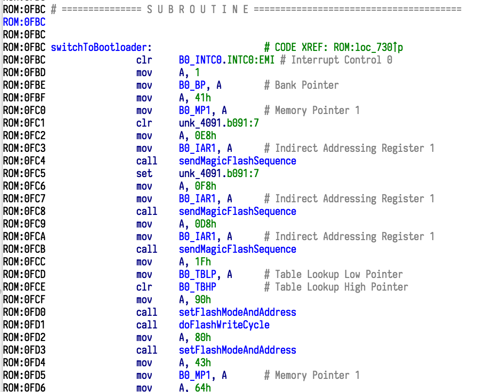
And just like that, there's our switch to bootloader function! Note how every direct use of a register like TBLP and INTC0 is annotated with the full name.
Bitwise Access
Remember, this CPU has those quirky little instructions that can operate on single bits of registers. On your typical RISC CPU, if you wanted to manipulate a single bit in a global variable, you might do something like this:
# Setting a bit
lwz r3, -0x2548(r13)
ori r3, r3, 1
stw r3, -0x2548(r13)

# Comparing a bit (if bit is set, call function)
lwz r3, -0x2548(r13)
clrlwi. r3, r3, 31
beq $+8
bl myCoolFunction
(Yes, I am fully aware that in the year 2018, 32-bit PowerPC isn't exactly the most typical RISC arch. I... I like it. Don't judge me. I blame me cutting my reverse-engineering teeth on GameCube/Wii games.)
On our wee Holtek chip, setting a bit is as simple as set [9Eh].0. Calling a function if a particular bit is set takes just two instructions: sz [9Eh].0; call myCoolFunction.
With as little RAM as this MCU has, space is at a premium, so packing as much data as you can into memory is vital. Most hardware access also involves working with individual bits in registers, so having an efficient and simple way to do that is highly useful.
Unfortunately, as far as I can tell, there isn't an elegant way in IDA to deal with these. You can create structures which even support concepts like unions, but they don't support bitfields. The type system used by the Hex-Rays Decompiler appears to support them, but we're working with plain old IDA, with an architecture that the decompiler will never, ever support.
I debated for a bit on how to handle these, looking at other example processor modules. The PIC module implements them solely by displaying bits loaded from a .cfg file, but this doesn't allow for customisation in the IDA interface. That approach is fine for hardware registers, but not when you're analysing code that makes heavy use of its own bit-packed variables.
I eventually settled for an approach using IDA's Enums and Netnode systems.
Default Registers
The first portion of this system is simple enough. I have pre-defined names for bits within all the hardware registers where bitwise access makes sense, and I've loaded these in from my JSON file, so I can go ahead and create enums for them when I'm preparing the database, after the HTRAM segment has been created.
        # define some enums
        bit_enums = {}
        for addr, reg in enumerate(REG_DEFS):
            if reg and 'bits' in reg:
                prefix = str(reg['name']) + ':'
                enum = add_enum(BADADDR, 'bit_' + str(reg['name']), 0)
                bit_enums[addr] = enum
                for bit, name in enumerate(reg['bits']):
                    if name:
                        add_enum_member(enum, prefix + str(name), bit, DEFMASK)
This gets us a bunch of pretty enums, like this:
FFFFFFFF # enum bit_BP
FFFFFFFF BP:DMBP0:        .equ 0
FFFFFFFF BP:DMBP1:        .equ 1
FFFFFFFF BP:DMBP2:        .equ 2
FFFFFFFF BP:PMBP0:        .equ 5
FFFFFFFF
FFFFFFFF # ---------------------------------------------------------------------------
FFFFFFFF
FFFFFFFF # enum bit_STATUS
FFFFFFFF STATUS:C:        .equ 0
FFFFFFFF STATUS:AC:       .equ 1
FFFFFFFF STATUS:Z:        .equ 2
FFFFFFFF STATUS:OV:       .equ 3
FFFFFFFF STATUS:PDF:      .equ 4
FFFFFFFF STATUS:TO:       .equ 5
FFFFFFFF
FFFFFFFF # ---------------------------------------------------------------------------
FFFFFFFF
FFFFFFFF # enum bit_SMOD
FFFFFFFF SMOD:HLCLK:      .equ 0
FFFFFFFF SMOD:IDLEN:      .equ 1
FFFFFFFF SMOD:HTO:        .equ 2
FFFFFFFF SMOD:LTO:        .equ 3
FFFFFFFF SMOD:FSTEN:      .equ 4
FFFFFFFF SMOD:CKS0:       .equ 5
FFFFFFFF SMOD:CKS1:       .equ 6
FFFFFFFF SMOD:CKS2:       .equ 7
Alright, so we've got these. Now, when I see the instruction sz B0_STATUS.0, I can highlight the 0 and press M and select bit_STATUS from the Enums list that comes up, and it'll turn it into sz B0_STATUS.STATUS:C. And if I decide I want to give STATUS:C a better name, like CarryFlag, then I can highlight it and press N and enter a new name, and it'll update everywhere in the disassembly.
Assigning these to Operands
But that instruction, sz B0_STATUS.0, is literally pointing to a hardware register that I know has an Enum. Can't I just have the processor module do that every time it sees a write? Yes.
We need to do that inside notify_emu, when we're processing the 'which bit' operand for these instructions. That seems straightforward, we can just look at the target register and figure out if we've created an enum for it. The tricky thing is that we need to store that information in a way that survives IDA being restarted.
We sort of had this issue when we made the HTRAM segment, but it was easy to work past because we could just call get_segm_by_name('HTRAM') and it would give us that segment. Long as the user keeps it named HTRAM, our code will work fine.
We don't want to rely on something as brittle as naming when we want to look up one of over 60 enums. This is where the Netnode system comes into play. It's a part of the IDA SDK designed specifically for this use case: allowing modules and plugins to store extra data. It's used by several other modules in the SDK, so there's plenty of examples, and the documentation inside include/netnode.hpp is also pretty good.
    def notify_init(self, idp_file):
        self.helper = netnode()
        self.helper.create('$ holtek')
        self.bitfield_enum_tag = 'b'
The first step is to create a netnode. We assign it the name $ holtek; starting with $ followed by a space is a requirement specified in the documentation. It's necessary to avoid conflicts with user-defined names in the database, since the netnode system is what IDA uses to store everything in an IDA database.
Each netnode essentially contains 256 arrays, identified by a single character (the 'tag'). We're using the one with tag b to store the enum that's tied to a particular data memory address.
There's a few different storage mechanisms you can use. I picked altval, "a sparse array of 32-bit values". Each enum's ID is a 32-bit value, so this works just fine.
        # fill all the register info in
        for bank in range(6):
            prefix = 'B%d:' % bank
            for offset, reg in enumerate(REG_DEFS):
                if reg and ('banks' not in reg or bank in reg['banks']):
                    ea = self.ram_addr + (bank * 0x100) + offset
                    MakeByte(ea)
                    MakeName(ea, prefix + str(reg['name']))
                    set_cmt(ea, str(reg['comment']), True)

                    if offset in bit_enums:
                        self.helper.altset_ea(ea, bit_enums[offset], self.bitfield_enum_tag)
Next, we alter the code that creates our registers. While creating the enums, we stored the enum IDs (the return of add_enum) into the bit_enums dictionary, but didn't actually do anything with the resulting dictionary. This is where we now use it: for each register, if there's a matching enum, we call altset_ea on the netnode (helper) to store that enum ID (bit_enums[offset]) against the register's linear address (ea).
We've got the information in, now to use it. The third and final step ties the whole system together, going into all the processing that occurs inside notify_emu.
        if op.type == o_imm and INSN_DEFS[insn.itype][IDEF_OP_TYPE] == HTOP_BIT:
            # make this an enum, if we can
            # TODO: ignore some like ACC maybe?
            # maybe also make sure we don't overwrite existing op_enums
            bit = op.value
            enum_addr = insn.Op1.addr
            enum_id = self.helper.altval_ea(enum_addr, self.bitfield_enum_tag)
            if enum_id == 0:
                enum_id = add_enum(BADADDR, 'bit_%03X' % (enum_addr - self.ram_addr), 0)
                self.helper.altset_ea(enum_addr, enum_id, self.bitfield_enum_tag)
            member_id = get_enum_member(enum_id, bit, 0, DEFMASK)
            if member_id == BADADDR:
                add_enum_member(enum_id, 'b%03X:%d' % (enum_addr - self.ram_addr, bit), bit, DEFMASK)
            op_enum(insn.ea, 1, enum_id, 0)
First, we make sure we only do this for immediate operands occurring inside an instruction that matches HTOP_BIT. Next, we fetch the data out of the instruction: for an instruction sz [9Fh].5, this would set bit to 5 and enum_addr to the linear address of data memory 0x9F.
Then, we ask the netnode if there's an enum assigned to that particular linear address. If there isn't, then we create one on-the-fly, and stick it into the netnode.
Then, we ask IDA if there is's a value in that enum for that particular bit. If there isn't, then we add one with a default name.
These last two things are the Cool Trick™️ that makes this system work for variables as well as the standard pre-defined hardware registers! If we ever see sz [9Fh].5 in the code, then we know that there must be some sort of significance to that bit, so we add it to the enums, turning it into sz [9Fh].b09F:5. Then, once the user thinks they know what [9Fh].5 stores, they can just smash the N key and enter a new name and it'll show up everywhere that addresses [9Fh].5. Amazing.
The last piece of this puzzle is to call op_enum - this is the programmatic equivalent of highlighting the number 5, pressing M and selecting the enum from the list.
The Result
Armed with this, IDA's restrictions become less painful. Take this register, for instance:
HTRAM:00F1 someUSBFlags:   SPACE 1                 # DATA XREF: ROM:loc_6C↑r
HTRAM:00F1                                         # ROM:loc_100↑r ...
I can't "drill down" into the individual bits and see what portions of code reference each one. I can, however, look at the cross-references window for the whole byte. Since the names now show up in the instruction itself, it's incredibly easy to see precisely what is being accessed.
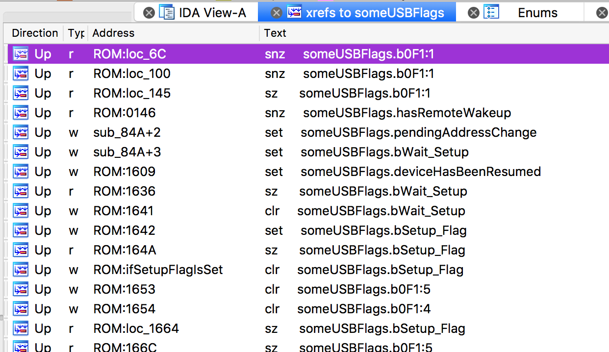
Blessed.
Detecting Jump Tables
A fairly common pattern when programming for this processor involves jump tables; the low-level equivalent of a 'switch' block. Take the code that handles USB commands, for example. You could implement this as a chain of comparisons - "if cmd is 0 jump to X, if cmd is 1 jump to Y, if cmd is 2 jump to Z, ..." - but it's much easier to use a jump table.
On this MCU, these are always implemented using the instruction addm A, PCL. This can be translated to pseudo-C as PCL += A. PCL represents the low 8 bits of the program counter (the address of the instruction that the CPU is currently executing), so that will jump ahead A instructions. This lets you do tricks like this:
addm A, PCL
jmp we_go_here_if_A_is_0
jmp we_go_here_if_A_is_1
jmp we_go_here_if_A_is_2
ret
Values of A from 0 to 2 will jump to those conveniently-named labels. If A is 3, we just execute ret and return. If A is higher than 3, we jump into no man's land.
IDA is pretty good at detecting different kinds of jump tables and 'switch' constructs, so I wanted to see if I could take advantage of this and create some nice handling for them.
There's a bunch of functions and structures defined in the SDK for dealing with switch statements. There's an entire page of flags for defining attributes that they can have. I spent a while trying to get this working, and in the end gave up - I got to the point where IDA would detect addm A, PCL and try to construct a switch statement, but rather than treating the table entries as instructions (jmp 04FAh, etc) it would turn the opcode into an invalid address.
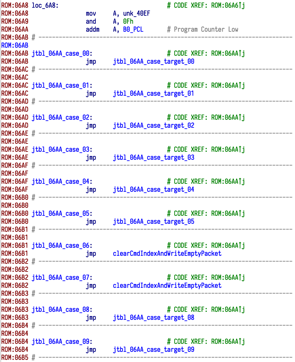
I ended up adding a check to notify_emu to detect the addm A, PCL sequence. It knows that the jump table always begins immediately after that instruction. There's an algorithm which tries to guess where the jump table ends, with some simple heuristics.
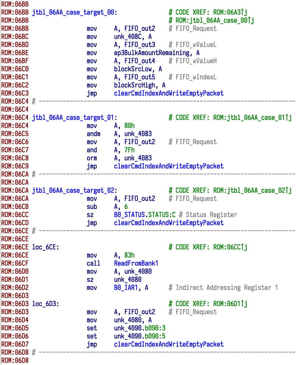
Once it's figured that out, it goes through every entry and gives it a name based off its index. If that entry is a jump to somewhere else, then that target location gets a name based off its index as well. This gives us verbose but helpful auto-generated names like jtbl_06AA_case_target_0A (that's the handler for command 0xA, reboot to bootloader) and jtbl_0DEF_case_target_00_01 (this one's used for both indices 00 and 01 in a particular jump table).
Finally, to make IDA's analysis work properly, add_cref is used to create a code reference from the addm A, PCL instruction to each jump table entry. Simple, but effective! Here's a couple of snaps of what the result ends up looking like.
Anything Else?
There's still things that could be improved in this module, but I think I've reached the point of diminishing returns. One weak spot is that there's no good handling for accessing registers and memory in banks above 0.
Fixing this properly would require more in-depth analysis of the code and trying to keep track of the current state of the BP, MP0 and MP1 registers at a given instruction. So whenever I come across code that deals with it, I have to do a bit of thinking and annotate things manually.
Likewise for table handling, there's no special processing for the TBLP and TBHP registers, or any attempts to create data references when data is read using the tabrd instruction. It's not very heavily used in my mouse's firmware (most of the table access is centralised in certain functions), so I figured the effort involved in implementing that would outweigh the time saving when figuring out that code.
The Next Step
So I've got a nice little IDA module now for disassembling this mouse's firmware. I'm ready to start digging into it and figuring out how it works! First point of call will be the USB data handlers, as I want to look for a way to get it out of this semi-bricked state.
You can find the tools I've created for this little project on GitHub, under a permissive licence - including the full code for this module: Treeki/TM155-tools
If you've really enjoyed this series of posts and want to help fund my hot chocolate habit, feel free to send me a couple of pounds: Ko-fi | Monzo.me (UK) | PayPal.me
Previous Post: Mouse Adventures #6: Enabling the Bootloader
Next Post: Mouse Adventures #8: Dissecting the USB Code and Unbricking the Mouse